I believe the framing around the heater and water heater was completed sometime in 2016. It took more than four years to get the drywall up, but here we are with a clean slate. This part of the railroad is the ore yard which is really an approach to the ore dock.
Heater enclosure before painting – November 8, 2020
There was some tricky trim work to be done and then more experimenting blending white and blue to get a realistic sky that is not distracting.
Heater enclosure complete – November 13, 2020
Now to block off the water heater without losing access. That should be a trick.
Sequence of Nov 18-20, 2020
There’s a whole lot more that got done between November 2020 and today (June 22, 2021). I’ll post those pictures later this week.
10 October 2020 – Some focused time with the benchwork and control panel
In an unexpected turn of events, my full-time employment ended as part of a reduction in force. This yielded some uninterrupted time to work on the layout for the past month and progress improved tremendously. Benchwork and a brand new control panel at Iron Mountain are the results so far.
Preparing to install fascia from Antoine to Powers/Felch Jct.
The first step was to prepare the benchwork to support the fascia from Antoine to Powers and Felch Jct. which is where the railroad will disappear behind the water heater. The routes split four ways at this point. The ore line can be switched to the ore yard and ore dock or bypass that for Escanaba (staging). The main line can be switched to go to Escanaba or directly to Green Bay. This loosely follows the prototype in 1962.
Fascia installed from Antoine to Powers and Felch Jct.Fascia cut for panel installation
The panel must be cut to receive the panel. There is also a Digitrax outlet next to the panel. A car card box will also be installed here.
Fascia Painted Green
The Fascia is painted to match the rest of the room.
Fascia at Antoine with decorations
The panel at Antoine is where the new fascia begins. The logos for the Milwaukee Road and the CNW are wood cuts that I’ve had for years. Nice to finally have a place where they belong!
Installed car card box
The car card box is installed. I modify these to hold bamboo skewers that are very good for uncoupling cars. Most of the sidings have uncoupling magnets below the track bed, but it doesn’t hurt to prepare for the worst.
Drilled panel
The control panel for Iron Mountain has been prepared in the photo above. This panel was challenging because it shares control with the panel at Antoine for many of the turnouts. This was accomplished by creating new JMRI inputs for the pushbuttons at Iron Mountain, but sharing the outputs from previously deployed Digitrax DS64s. I presented to the Michiana Division of the National Model Railroad Association (NMRA) on this topic in April 2020. One of these days I will post the presentation here.
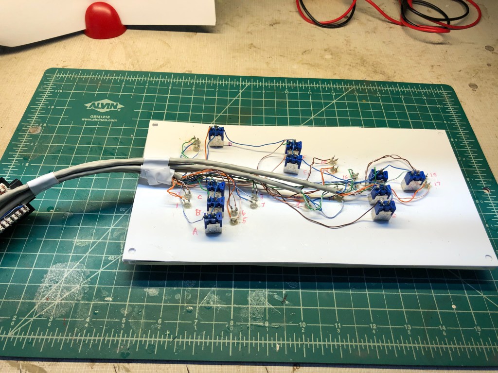
Back of Iron Mountain control panel
The photo above shows the completed wiring on the back of the panel. Each pushbutton and LED are labeled. Ethernet cable is used to connect each wire to a punchdown block. This makes connecting the wires on the layout easier and also allows for the panel to be removed for maintenance if necessary.
The layout has 45 tortoise machines installed to date and each of them are controlled by a pushbutton on a control panel. There will be close to 70 installed when the layout is complete. The aspect of the tortoise machine and the turnout it controls is shown on the control panel by dual bulb LEDs that show green or red based on the polarity of the signal coming across the led from the DS64 to the Tortoise machine. I have installed at least 100 LEDs on the layout. Last week I finally found a bad one. The red/green LEDs actually contain two circuits which are directional based on polarity. That little problem cost me a couple of hours as I tested and retested every connection. I finally decided to replace the LED and that was the problem. Nobody is perfect.
Deployed panel at Iron Mountain
Shown above is the panel at Iron Mountain. It works just as it was designed to work in conjunction with the panel at Antoine. This will allow two operators to work together over this stretch of the railroad without needing one to ask the other to throw a turnout. Both operators will be able to see the aspect of every turnout that impacts their work. It will require that operators be aware that these turnouts may be thrown from the other panel.
Completed fascia with panel
There is still much to do to complete the railroad to Powers and Felch Junction, but the track, control panels, turnouts, and fascia are complete. The next project will be to complete the drywall and framing to hide the water heater and build the benchwork to support the ore yard which leads to the ore dock. Stay tuned!
2 SEP 2020 – A Diversion – Building a Simple Walthers Kit
Last month I got the river onto the layout. There’s still work to do there, but for now I can run trains over both bridges. Seemed like a good time for a little diversion.
Bridges and tracks in place
I learned there was a motor lodge in Quinnesec that still operates called the Hillcrest Inn. I had a Walthers Kit for the Hyway Inn. I also learned that in Iron Mountain there was a place called The Vagabond Inn that was made up of individual cabins like the Walthers model. I decided for my purposes The Vagabond Inn was a fitting name and so we would alter history a bit and place this motel on the banks of the Menominee.
Using the base of the model, I built foundations on a small piece of 1/4″ plywood I had laying around and test fit it to the area. Enclosing this with a grove of trees would separate it from the taconite mine (Groveland) and the hydroelectric plant and create some depth in this area of the layout.
Foundations for the office and cabinsTest fitting the scene to the layout
The motel base didn’t fit perfectly with existing benchwork so I cut a hole in the cardboard mesh and hand sawed an opening in the 1/2″ plywood base.
Making room
Beneath the layout I added a joist to hold two risers that would keep the motel’s foundation secure.
Securing the base
The kit includes two cabins, an office building and a propane tank. It also includes a sign, but I will be scratch building a sign later. The propane tank in my world has a personality
Smile!
The model was easy enough to build and weather. Getting it integrated onto the layout took some effort.
The model on the layout
Next steps will be to add scenery. A grove of deciduous trees will separate the motel from the models behind it. Some decorative conifers will be placed around the motel grounds to spruce things up. Model railroading is fun!
29 JULY 2020 – More paint and a test fit to the layout
The past five days have seen the water feature and hydro electric plant begin to take on their final appearance. I did not like the cement piers that I made out of foam. They did not look convincing and detracted from the rest of the water feature. The foam was needed to create the elevation required to meet the legs of the bridge, so I shaved them into mounds and covered them with talus and paint.
The concrete piers modified for better appearance
I added fencing and detail to the hydro electric plant also. The paint on the fencing doesn’t match at this point so there is still some work to do.
With all of the modifications I had made over the past few months while the piece was on the workbench, I was concerned that it might not fit perfectly on the layout. It turns out that it fits pretty well. The adjustment to the power distribution equipment on the mine side of the river will require the mine tracks to be adjusted, but that should not cause any problems.
The water feature is added to the layout
This picture looks remarkably like the Photoshop version that I created at the start of this project! Next steps are to adjust the bridges so that they meet up perfectly with the track on the layout and blend the scenery into the layout. After that the piece will be removed for pouring of the water and final scenery adjustments. It will then be brought to a meeting for judging and then place on the layout permanently. We’re probably about two weeks away from running trains again!
23 JUL 2020 – Fabricating the Cyclone fence around the power distribution equipment
The Walthers kit that was used to build the power distribution includes materials for a Cyclone fence to surround the equipment. The fence is made to enclose the entire kit and I’m only using a third of it or so. The other variation is that I want the gate to open inward from the dam which does not line up with the holes pre-drilled for the fence posts. The kit includes vertical posts made of styrene with details on them, the wedding veil material for the fence itself, and some metal rod to be used for the cross members at the top and bottom as well as two styrene gates.
The Walthers instruction is to attach the vertical posts to the base, glue the horizontal bars to the posts with CA, paint the veil material, and then apply it to the fencing with CA. This sounds like a mess, especially since the equipment is already installed and painted.
Mitch Maynard recommends building the fence posts all out of metal rod and soldering it using a wooden board upon which the fence section has been drawn. The fence is assembled in sections and painted in the spray booth and then installed on the base.
I’m trying to decide if the detail on the styrene fence posts is worth trying to use a combination of methods, or if I should just use Mitch’s method. I have enough material to try it both ways. I think I’ll try Mitch’s method first.
Meanwhile the river bed is coming along slow but sure. The fence will give me something to do while paint and glue is drying.
21 July 2020 – Two months of progress on the hydro electric plant and water feature
What fun we’ve had since the last update at the end of May 2020. The first photo shows the debarker and chipper buildings have received paint. They are white with steel tops. A later photo will show they’re a little rusty. There will ultimately be a conveyor under the debarker to take the bark off somewhere to be converted into fuel. The conveyor is built, but some modifications must be made to make it fit.
Here you can see that a power distribution grid has been placed to the one side of the Menominee River. This is all proto-freelanced, so I have no idea how they got the power to the paper mill. I do know that the hydro plant is still operating and providing power to Wisconsin Electric, so there must be something like this set up. This will provide a nice transition into the scene to the right of this which is the Groveland Taconite Plant.
Here the guardrails and some signage has been added to the debarking building.
This little building came with the sawmill outbuildings kit. I tried it under the power distribution equipment, but have since moved it to the back of the debarker. I imagine that there are some gears that are driven by the turbines underneath the hyrdro plant and these gears transfer power to the teeth of the debarker. This little building is what keeps this equipment safe and dry.
The hydro electric plant is mostly imagined but I did look at some pictures. I figure this one works by lifting these big steel and concrete panels to let water through. I will be adding guardrails and also H steel beams above the panels with augers and wheels so that they can be adjusted up and down. The stairs are there so that the crew can maintain these panels when needed. In reality it’s all stationary of course.
The guardrails were from another kit and happened to fit. I have more on the way. The cement steps were made by cutting pieces of polystyrene into blocks and gluing them together. It was a bit monotonous but fun.
Painting the plaster was fun. Most of the plaster outside the river bed will be covered with ground goop, static grass, flocking, trees and underbrush, but painting it was good practice and also allows some flexibility when the other materials are added.
I have decided to separate the legs of the bridge from the platform so that I can align the legs perfectly to the cement piers and then adjust the bridge platform so that it aligns perfectly with the track on the layout. This will require that the module be put on the layout. I’m hoping to do this by the end of the month and finish the module well enough to remove it one time and bring it to a Michiana Division NMRA meeting for my friends to see. After that, it will be returned to the layout and permanently installed.
The glue is drying on the talus I added to the lower section. The talus is being painted a mix of reds, browns, and tans. I will add some submerged trees and further adjust the paint on the river bed and then pour that section with resin. I haven’t quite figured out how I will pour the middle and upper sections, but where there’s a will there’s a way! Stay tuned!
After assembling the chipper building and the debarking shed from the Walthers Sawmill Outbuilding kit, I need to figure out how the buildings would work in the small space that I had to transition from the hydro plant to the pulp tanks. The chipper building came with a conveyor which was meant to take the debarked pulpwood from ground level to the top of the chipper. After a few experiments it dawned on me that I could use the elevation between the hydro plant and the paper mill to eliminate the need for the conveyor. The chipper building would provide the transition. I modified the debarking shed to include a debarker that is made from an extra smokestack I had from another project. In theory, when pulpwood is delivered to the paper mill, it is transferred to the log pond that is formed as part of the dam. The current of the river naturally moves these logs toward the debarker which is located next to the dam. Pulpwood from the log pond is conveyed into the debarker which deposits the bark on another conveyor where it is retained for fuel. The logs continue into the chipper where they are ground into fine wood chips and then blown into the pulp tanks. Here are some photos of the progress.
Creating the base for the debarking shedEstablishing the height for the chipping buildingPlacing the debarking shedAdding the debarker to the shedModified roof on the chipper since the conveyor is not usedDebarker and chipper work together
I have moved the doorway for the chipping building for safety (the door as pictured would lead to a rail siding – very dangerous). The stone bridge over the ore line will be completed, painted and weathered and it will be time to start work on the water.
18 MAY 2020 – Removing the Module – Fun with Plaster
The big challenge today was to see if I can still remove the module now that all of this foam has been added. The answer is yes! The module came out and now I can add plaster, resin, the bridges, and the hydro plant and then replace it for laying track.
I have had a role of Scenery Express plaster gauze for several years and I finally got to use it. I also have a gallon or so of Hydrocal and some molds from Woodland Scenics. I have never gotten it to work right and today was no exception. I think I’m using too much water. Back to the drawing board!
The module has been removed and placed on a table for the next stepsAdding plaster gauze is a lot like making a cast for a broken boneThe bridges still fit. We are ready to start adding some outcroppings and embankments.
The last several work sessions on the river have it ready for plaster, painting, and pouring of resin. The pictures below show the step by step progression as foam was added piece by piece to create the illusion of limestone that has been eroded by the river at the falls.
Midway through the construction it became apparent that a second drop would be required in order for the bents of the curved trestle to appear natural on their concrete piers. The falls will not look exactly like Quinnesec, but they will look at home in northern Wisconsin. The second drop will also allow for some additional water effects that should add visual interest.
All foam was added to allow for the seams to ultimately be hidden, but for the river and attached hydro plant including the debarker and chipper building to be removed without damage. Our next step is to remove the river an see if it was built properly.
After removal, the plaster, ground goop, paint, and resin will be added to form the river and surrounding scenery. The hydro plant and chipper de-barker building will also be designed, constructed, painted and weathered. The entire section will then be placed on the layout and the track across the bridges will be installed including adjustments to roadbed and ballast where appropriate.
Step one: placing the bridges and embankmentsStep two: both embankments supported by foamStep three: creating the mine-side river bankStep four: filling in the lower part of the mill-side river bankStep five: adding a secondary drop to the river bed and beginning to fill in mill-side of river bankStep six: Ensuring the river bed is correct for the curved trestleStep seven: The riverbanks are complete and ready for plaster and paintStep eight: Placing the bridges on the completed river banks – time to remove the module!
Continued working the river bed to support the bridge embankments. The photo below shows the embankments are in place and supporting the bridges at the correct height. Next steps will be to continue to place foam in a manner that supports the flow of the river around these embankments. It’s slow going, but lots of fun and exciting to know that once these are in place, it will be possible to restore the track and put the lines back in service.
Both bridges supported at correct height by river banks and embankments